
Table of Contents
ToggleLaunching a high-fidelity virtual construction sequence relies entirely on anchoring your baseline coordination around pristine spatial data. The reality across the sector is that heaps of active contract scopes are still disabled by legacy flat vector CAD blueprints. With data-rich model adoption accelerating across global markets, processing those old drawing stacks via a clean DWG to RVT pipeline is a mandatory rule to keep your property assets competitive.
Operating a dedicated DWG to RVT tracking system translates vector lines into multi-layered parameter matrices, instantly driving up your spatial layout precision and multi-trade synchronization. What’s more, following a disciplined, structural processing route systematically deletes drawing clash anomalies before the site trades mobilize, allowing design consultants, engineers, and building contractors to operate on the same canvas.
Current reality-capture guidelines enforce zero-tolerance metric tracking, strict object hierarchy logs, and immaculate construction handovers. Because of those targets, mapping your data migration step-by-step pumps immense operational velocity straight into your project from initial massing blocks right up to sign-off.
No matter if your spreadsheet targets a boutique residential layout, a sprawling commercial block, or a heavy-clearance manufacturing shed, running an authoritative DWG to RVT pass locks down an unyielding infrastructure baseline for eventual structural additions. The direct payout is that your modeling room cuts out hours of frustrating rework loops while maximizing your system stability across the asset lifecycle.
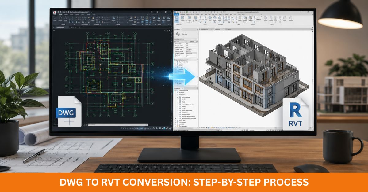
Understanding the DWG to RVT Conversion Process
Pulling off an audit-proof file overhaul demands a thorough pre-start review of the source data. Every sheet length must clear an extensive layer check prior to dropping the first wall tool; setting up clean vector tags, verified baseline scales, and stripped-down blocking grids ensures your finished structural environment mounts flawlessly without layout sags.
The technical workflow shifts vector lines away from old, flat drafting representations to anchor true parametric objects inside the model space. Far beyond basic polyline sketches, these objects hold deep material data sets, meaning partition assemblies, slab levels, fenestration units, trusses, and structural framing tails function as smart, interactive code blocks rather than boring pixels.
The raw baseline cleanliness of your input vector lines entirely dictates your processing speed on the workstation. Because of that data weight, you need to ruthlessly purge parasitic layers, overlapping paths, and dead block clusters before importing anything into your work files, a cleanup strategy that slashes modeling time while pinning your metric precision down to the millimeter.
A ton of advanced technical teams aggressively migrate legacy block definitions into an explicit 3D DWG to Revit family format while the project tracks through setup. Transforming old solids into parameterized, reusable components locks in absolute material uniformity across multi-site retail expansions or institutional developments, optimizing your draft production speeds completely on autopilot.
Some international projects require DGN to Revit conversion before BIM development begins. Similar preparation methods apply because organized source files always produce better modeling results. Proper planning also supports clash detection, quantity take-offs, and construction documentation later in the project.
Preparing CAD Files Before Starting DWG to RVT
Preparation often determines the final quality of every DWG to Revit conversion. Even experienced BIM specialists spend significant time reviewing source files before importing them into Revit.
For starters, every source file must align natively with a single, uniform unit system. Mixing metric and imperial limits down in the coordinates causes massive scaling bugs the second the data lands on your workspace, making pre-import parameter checking your best weapon to avoid high-cost drafting modifications down the line.
Next up, streamline your source vector indexing maps by deleting legacy text notes, buried geometries, obsolete survey marks, and double lines before you hit the import key. Doing this manual sweep strips away unneeded data weight, keeping your central work file beautifully lightweight and preventing memory tracking lag on your machines.
Nested drawing callouts also demand strict operational auditing before conversion. Dead attachment tracks or missing external links routinely yield blank, out-of-spec zones inside your workspace, proving why verifying every single background file link secures absolute spatial precision across the entire production track.
A major secondary checkpoint focuses on hunting down broken geometric paths. Double-struck lines, unjoined wall intersections, and erratic label metrics will always throw error codes during extrusion phases, and fixing these vector faults early eliminates drafting friction to secure pristine model stability.
Scopes that target a heavy 3D DWG to Revit family transformation track require lightyears deeper indexing look-overs. Raw solid files need to track clear, standard labeling systems because a cleanly mapped component ledger simplifies your long-term model administration, an identical rule that your tech desk must apply before routing any native DGN to Revit streams through your modeling bays.
Importing DWG Files into Revit Correctly
Slipping data into the workspace sounds like a basic one-click step, but a sloppy baseline link regularly causes massive coordination blowouts down the line, requiring your modeling managers to execute an airtight, multi-stage link routine.
The source link vectors must map directly to your real-world Shared Coordinate system. Sinking your master datum onto the exact site survey markers anchors flawless multi-disciplinary cross-talk across the building lifetime, whereas a minor placement deviation throws your structural steel out of alignment during automated clash scans.
Managing your active layer display profiles is another key task, given that flooding the model space with junk notes bogs down your display frame rates. Isolating only high-priority structural paths gives your drafters a crisp, fast interface. From there, run a rapid scale audit over your grids, checking individual vector parameters straight against hard dimension callouts to ensure minor scaling glitches don’t warp your final shop drawing exports.
The second, the link links flawlessly over the project origin points, and the design team begins building a true digital twin by tracing smart components over the underlying vector lines. Core wall skins, slab plates, roofing systems, steel columns, load-bearing beams, and joinery units systematically replace dead flat lines with live, parametric components.
This production block unrolls the perfect window to execute a clean 3D DWG to Revit family transformation if your original drawings pack custom structural components. Building a library of clean, parameterized smart assets keeps your corporate naming standards immaculate while reinforcing your long-range model updates.
Creating Intelligent BIM Elements During DWG to RVT Conversion
The real value of CAD to Revit conversion appears when static CAD lines become intelligent BIM components. Every modeled element carries information that supports design, construction, and facility management. Therefore, the model becomes much more than a digital drawing.
Every structural object pulls high-fidelity classification fields as it is generated, assigning exact core thicknesses and acoustic ratings to partitions, packing dimensions into door schedules, and locking clear head clearances onto window instances. This granular tracking enables your database to turn out instant material takeoff schedules while driving up blueprint accuracy.
Main engineering elements demand identical close checkups on the grid. Concrete pillars, structural beams, deck levels, and pad footings must lock precisely onto the source coordinates while satisfying standard model structural configurations, a cross-discipline uniformity that flattens coordination errors on site.
Bundling your workflows right with targeted 3D DWG to Revit family conversion fields injects massive operational agility into your asset files. Holding a repository of clean, standard components cuts layout guesswork out of the matrix during future design overhauls, allowing your drafting room to run design updates light-years ahead of old speeds.
Services layouts, duct tracks, and schematic pipe loops similarly extract massive performance gains from parameter modeling. Far ahead of broken, disconnected lines on a flat page, every mechanical component hooks into a single, cohesive spatial engine, allowing MEP engineers to execute automated interference scans and kill site installation delays dead.
Accurate BIM models should also align with Australian building information standards for compliant construction documentation.
Quality Checks After DWG to RVT Conversion
Running a rigorous engineering audit stands as the absolute cornerstone of your delivery pipeline, given that even a highly clean modeling pass requires deep-dive data checking before you sign off on the files.
The opening quality pass runs a side-by-side verification check comparing your fresh model straight against the raw input vectors. Core dimensions, grid boundaries, finished floor milestones, and steel columns must register a flawless 1:1 match, because a tiny millimetric shift here will launch a massive structural catastrophe at the construction face.
From there, the modeling managers execute a thorough visual telemetry sweep across all sectional views. Any hidden drop-outs, double-modeled geometries, bad level assignments, or floating objects are completely purged before the project moves to final approval.
Data extraction filters need strict validation checks; internal opening matrices, spatial volumetric counts, and material finishes must calculate pristine quantities right through the project file. Immaculate database scheduling strips the tech stress straight out of your quantity surveys, streamlining material procurement and pricing tasks. Simultaneously, your audit needs to target itemized catalog sorting, ensuring that every standalone 3D DWG to Revit family tracks a clean, standard naming code to protect your spatial management through future design updates.
Running rigorous file optimization checks is another key step to boost your system health. Lean, lightweight project configurations open within seconds and navigate flawlessly during cloud coordination meetings, which is exactly why you need to flush out redundant CAD links, dead family types, and over-modeled vertex paths to flatten your file size.
The final stage relies on pulling separate architecture, framing, and mechanical models into a centralized cloud coordination space to check for geometric overlaps. Running early automated collision detection drives down high-cost variations in the field, helping your team turn out an unyielding project handover on time.
DWG to RVT Workflow Comparison
The table below highlights how a structured DWG to RVT process improves project quality compared with using traditional CAD drawings alone.
| Feature | Traditional DWG Drawings | DWG to RVT Conversion |
|---|---|---|
| Model Intelligence | Static 2D linework | Intelligent BIM objects |
| Collaboration | Limited | Excellent multidisciplinary coordination |
| Quantity Take-Off | Manual calculations | Automatic schedules |
| Design Changes | Time-consuming | Faster model updates |
| Clash Detection | Limited | Built into BIM workflows |
| Documentation | Separate drawings | Connected documentation |
| Facility Management | Minimal support | Long-term asset information |
| Project Accuracy | Moderate | High precision BIM model |
This analytical side-by-side review hammers home exactly why premier engineering groups are dropping flat drafting models completely. Committing your data to an advanced DWG to RVT pipeline jacks up your overall production speed while squeezing out structural liability risks from your project folder.
Best Practices for Successful DWG to RVT Projects
Successful DWG to RVT projects follow proven industry practices from beginning to end. Consistency always delivers better BIM models. Securing pristine vector source files stays positioned as your number-one priority line item, given that an immaculate CAD database slashes extraction errors and speeds up your modeling room’s turnaround times, proving why skipping the cleanup phase is a fatal mistake.
Dropping your project onto a strict corporate template locks down uniform line types, shared parameter sheets, standard element tags, and clear layout definitions across the whole office. Squeezing in a rapid model performance scan every few weeks maintains file health, cutting out background corruption vectors to ensure a clean multi-user environment.
Tracking file iterations and model updates demands identical close management in your logbook, ensuring every drawing issue carries a clear, traceable modification tag. Holding that transparency prevents version mix-ups while shielding your core intellectual data assets. Open, high-velocity data sharing between designers, structural teams, and model managers streamlines the processing steps, checking off your communication targets to kill off unneeded drafting revisions.
Ultimately, running continuous technical checking guarantees that every single phase of your DWG to RVT pipeline aligns perfectly with the client’s spatial requirements before delivery. This data-first discipline provides a flawless parametric foundation across townhouse packages, shopping complexes, manufacturing zones, and civil infrastructure overhauls.
Conclusion
Moving your assets through a specialized DWG to RVT setup yields a massive long-range return on investment far past a basic format swap. It hands your facility team an intelligent digital twin that drives operations right through the asset lifecycle, combining precise spatial accuracy, unified team cross-talk, and slick file performance across the timeline.
Immaculate source files, precision extrusion rules, deep quality audits, and structured component libraries are what unlock elite project metrics. What’s more, fusing custom 3D DWG to Revit family components directly with advanced DGN to Revit conversion paths builds an ironclad level of model uniformity across entirely separate building types, serving up an invaluable asset tool for corporate developers, mechanical leads, site crews, and asset managers worldwide.
Contracting a specialized firm to manage your DWG to RVT processing slashes structural data risks while keeping massive blocks of design time inside your studio’s calendar folder. An audit-proof model allows for blazing-fast design updates, automated collision scanning, rock-solid quantity take-offs, and clean vector blueprint exports, handing every stakeholder an optimized digital pipeline that holds its capital worth for decades.
Looking for accurate and reliable DWG to RVT conversion services? A professional BIM team can transform existing DWG drawings into intelligent Revit models with exceptional precision and fast turnaround times. Every model follows industry standards while supporting seamless collaboration across architectural, structural, and MEP disciplines. Contact us today the team today to discuss project requirements and receive a customised quotation for high-quality DWG to RVT conversion services.
Frequently Asked Questions
Why is DWG to RVT important for BIM projects?
Swapping old flat lines for an automated parametric mesh entirely drops unneeded spatial coordination errors straight out of your budget logs, utilizing structured objects to optimize your project timeline without causing a single drop in documentation quality.
Can 3D DWG to Revit Family conversion be included?
Spot on. Sinking capital into an advanced 3D DWG to Revit family transformation maps legacy blocks straight into flexible, shared components, keeping your drafting room’s performance metrics perfectly sharp across multiple distinct project layouts.
Is DGN to Revit conversion also available?
Absolutely. Sourcing your layout parameters through an expert team allows you to route native DGN to Revit pipelines without losing your original spatial variables, helping your development team achieve a clean model handover across completely separate software suites.
How long does a DWG to RVT conversion project take?
The full geometry analysis, manual parametric tracing run, component cataloging, and final multi-discipline clash reviews move across a structured schedule dictated by your source asset files, an explicit trade progression built to return an immaculate virtual asset built for life.